Practical astronomy projects for every level of expertise
DIY Astronomy
Build a zero-magnification finder
Make an illuminated aiming device you can use on any telescope
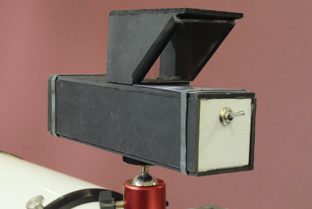
This month’s project helps you aim your scope at a target in the night sky. It is called a zero-magnification finder because the view is the same size as seen with your naked eye. The finder projects a red circle onto the background sky and you move your telescope to align the centre of this circle with your target. Many stargazers use similar devices because they allow you to keep both eyes open and see a much larger area of sky, making it easier to jump to the target.
Our design has a red LED that illuminates the white interior of the front of the case. The LED is powered by a coin cell battery, via a switch on the back panel. The red light is reflected backwards through a clear glass screen, painted matt black except for a small ring in the centre. The light is then reflected upwards by a mirror mounted at 45° and through a lens, which produces a sharp image. This is reflected backwards again by a glass viewing screen, mounted at 45° in a hood. When the distant sky is viewed through this screen, the red circle is superimposed on it.
We sourced the components for this project imaginatively to keep the cost down. The LED, coin cell holder and switch are from an educational supplier. The clear glass was cut from an old picture frame, and we used the frame’s thin MDF backing to make the case. The front surface mirror is a disposable dentist’s mirror. We found these online, along with the lens, a Fresnel magnifier sheet.
Mounting matters
Cutting glass is easy – score with a glass-cutting wheel and snap over a straight edge – but it is advisable to dull the resulting sharp edges by rubbing on a flat stone. Alternatively use clear plastic, which can be cut from an old CD case.
Once you have made your finder, you’ll need to mount it and align it with your telescope. We used a camera ball mount for this. The top screw passes through a hole in the bottom of the case. Use a ¼-20 nut to fix it. Alternatively, a blob of hot glue will suffice. To attach the ball mount to the scope, use a ¼-20 stud (some mounting rings have screw-threaded holes for attaching accessories), or improvise with a large pipe clip or cable ties to hold the hot shoe part of the ball mount. Point the scope towards an easy-to-find bright star or planet, loosen the ball mount and align the projected red circle with the same target. Once aligned, you can use the finder (along with your Sky at Night Magazine all-sky chart) to hop around the sky with ease.
What you’ll need
►Ruler, square and pencil for marking out.
►Coping saw, junior hacksaw, drill, drill bits, glass cutter, cutting mat, soldering iron.
►Small sheet (approximately A4 size) of thin MDF or plywood; small piece of thin glass or clear plastic; small metal ring (8–15mm or so in diameter).
►Red LED, 3V coin cell battery, battery holder, toggle switch (single pole, single throw), short length of electrical wire.
►Dentist’s mirror, Fresnel credit-card-sized magnifier.
►Camera ball mount.
►Spray paint, glue (we used a hot-glue gun), black paint, white paint.
Step by step
Step 1
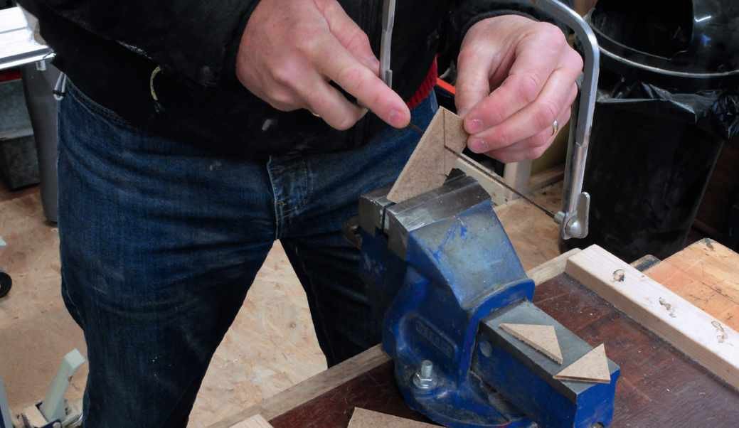
Carefully mark out the MDF (use our downloadable plans to work out the sizes). Cut out all the parts with a coping saw or similar, then sand the edges smooth. We used 3mm MDF, but any thin board should work. Keep close to our suggested dimensions.
Step 2
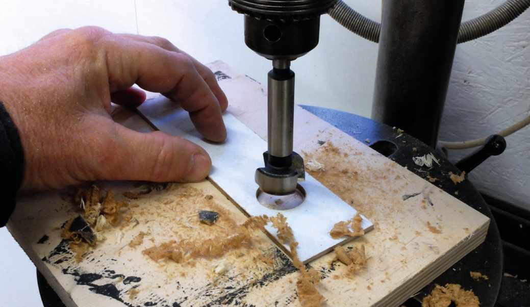
Carefully drill the holes in the panels. You need a hole of approximately 20mm diameter for the reticule aperture and a similar size for the top of the main case. This could be cut with a coping saw if you don’t have a large drill.
Step 3
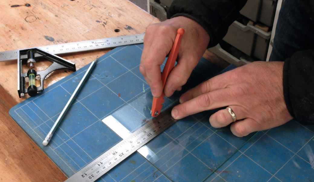
Carefully cut the glass for the reticule and viewing screen. Use a glass-cutting wheel to score a line, then press down over the edge of a ruler to snap it. We used a flat stone (normally used for sharpening chisels) to dull the sharp edges.
Step 4
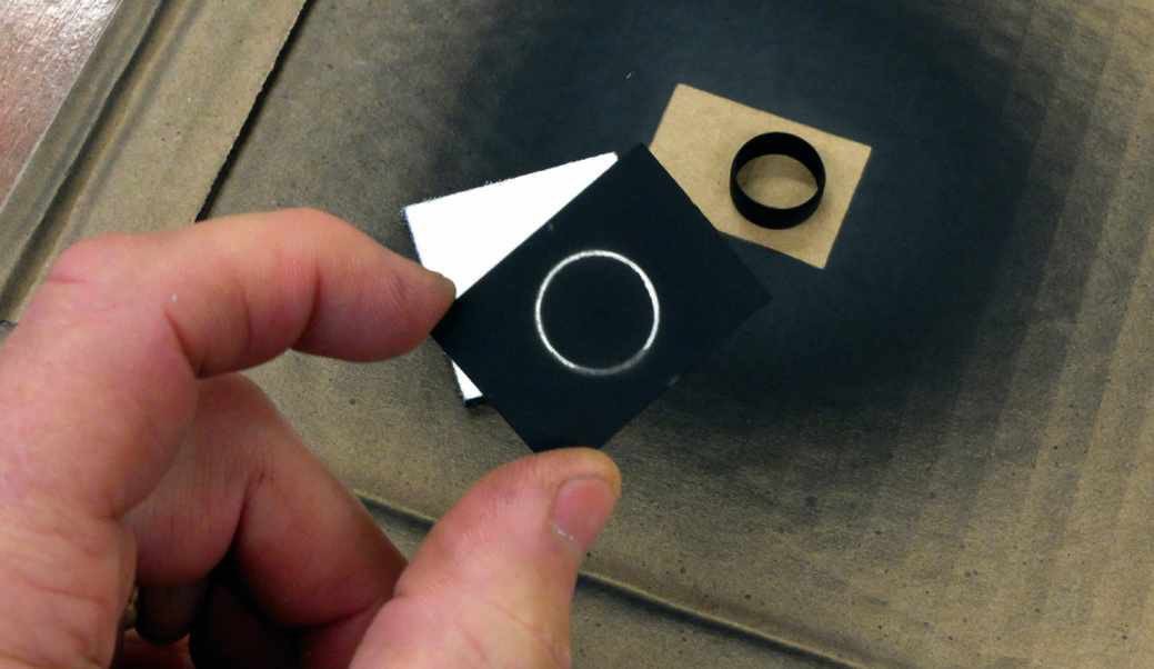
Place a small metal ring (say, a plumbing olive) on the reticule glass then spray it matt black. The ring masks off an area of clear glass to form the pattern. You could experiment with other objects to create crosshairs and other shapes.
Step 5
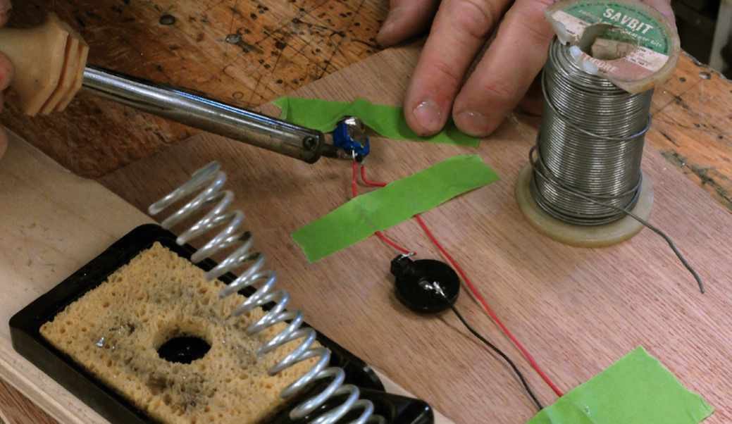
Use your soldering iron to wire the cell’s positive terminal to one switch terminal, then the other switch terminal to the positive (longer) leg of the LED, then the negative LED leg back to the negative cell terminal. Check it works before fitting into the case.
Step 6
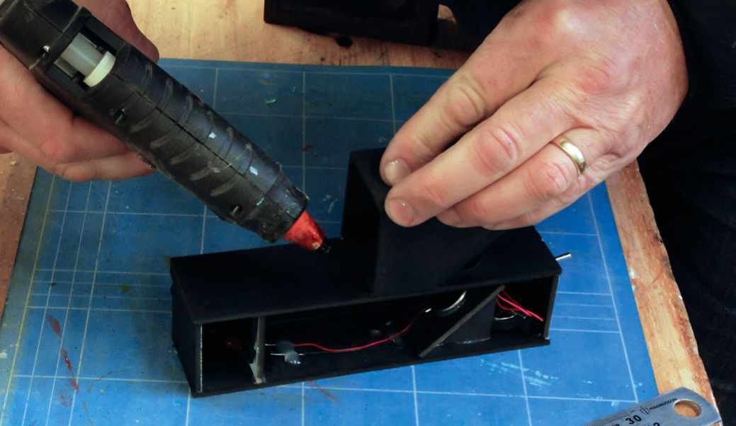
Join the case together, including the reticule and mirror mount inside. Add the mirror, aligned so it reflects up through the hole above. Glue the screen and trimmed Fresnel lens in place. We held the side panel with rubber bands, for easy future access.
MORE ONLINE
Visit our Bonus Content to find additional photos and download diagrams to help with your build.

Mark Parrish is a bespoke designer based in West Sussex.